Operating Modes
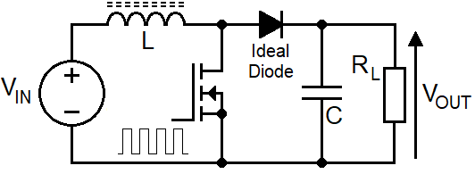
The boost circuit can operate in either of two modes but, the voltage transfer equation is different for each mode.
Therefore, to calculate duty cycle (D), it is necessary to establish the operating mode so that the correct formulas
can be used. The two operating modes are: -
-
DCM (discontinuous conduction mode) - the inductor current will fall to zero amps. Accommodates light to medium load currents.
Duty cycle lower than CCM
-
CCM (continuous conduction mode) - the inductor current remains above zero amps. Accommodates medium to heavier load currents.
Duty cycle higher than DCM
Discontinuous Conduction Mode
DCM has three distinct phases per switching cycle; charge, transfer and hold. The length of the hold phase accommodates
changes in load current: -
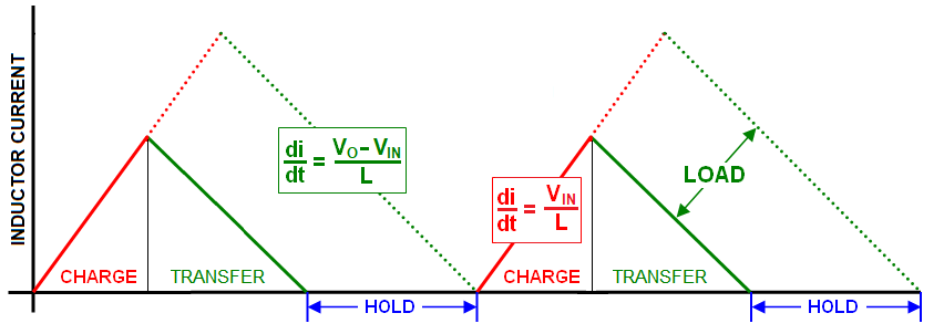
The "hold" phase begins when all the inductor's energy is transferred to the load. If the load requires more energy/power,
then the "hold" period must shorten and the charge/transfer period will increase. If the load requires less energy, then
the "hold" phase increases.
-
To maintain the desired output voltage, duty cycle is continually adjusted to accommodate load current changes.
This is the function of "the controller"; it adjusts duty cycle, \(D\).
-
The slopes of the currents (\(\frac{di}{dt}\)) are non-negotiable because they are defined by the input and output voltages
as per Faraday's law of induction.
-
If the input voltage reduced by 10%, the current charge slope (red) also must reduce by 10%.
-
If the output voltage requirement increased by 20% then the current transfer slope (green) must also increase by 20%
-
If the input voltage changes, duty cycle must also be adjusted to maintain the correct output voltage for a given load current. This is also true for CCM operation.
-
If the hold-phase becomes zero and the load current demand is still rising, DCM will "slip into" CCM. This can sometimes cause output voltage instability.
Continuous Conduction Mode
CCM has just two phases; charge and transfer. Load current changes are accommodated by the whole of the inductor current waveform rising or falling: -
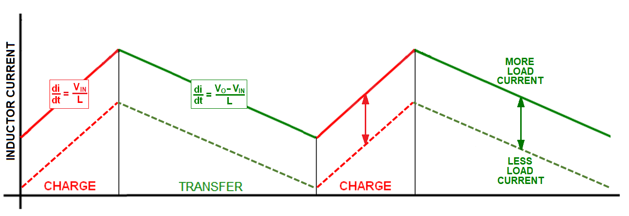
CCM doesn't have a "hold" phase because it's continually charging and transferring energy however, here's a reminder of an important thing: -
$$\color{red}{\boxed{\text{CCM and DCM have different voltage transfer equations}}}$$
This means that for a given load and duty cycle, DCM won't deliver the same output voltage as CCM. This is an important distinction.
CCM and DCM summary
- Only one mode delivers the correct \(V_{OUT}\) to the load for given values of \(V_{IN}\), \(L\) and \(F_{SW}\).
- Lighter loads are usually serviced in DCM.
- Heavier loads are usually serviced in CCM.
- CCM is a natural outcome when DCM can't service the heavier load.
- DCM is a natural outcome when CCM can't service the lighter load.
The next step is to decide which operating mode fulfills the requirements of a proposed design.
To perform this next step we consider the boundary condition. This is where DCM meets CCM; the inductor has delivered all it's energy to the output and
the switching cycle restarts immediately. We then need to ask this hypothetical question: -
$$\color{red}{\boxed{\text{At the boundary, is the power delivered to the load sufficient to sustain }V_{OUT}}}$$
If the answer is yes, then we will operate in DCM. If the answer is no we will operate in CCM.
Boundary Condition
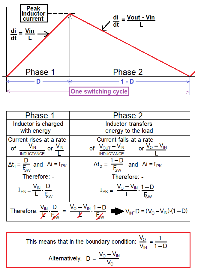
Right at the bottom of the above picture is an important formula: -
$$\boxed{D = \dfrac{V_{OUT}-V_{IN}}{V_{OUT}}}$$
And, from \(D\), emerges the charge time, \(\hspace{1cm}t_1 = \dfrac{D}{F_{SW}}\)
Question: How much energy can the inductor acquire during \(t_1\)?
Answer: We must start by finding the peak inductor current (\(I_{PK}\)).
Calculating \(I_{PK}\) in the boundary condition
Using Faraday's equation for an inductor we know: -
$$\boxed{V = L\cdot\dfrac{di}{dt}}$$
Where,
- \(V=V_{IN}\)
- \(di=I_{PK}\)
- \(dt=t_1\)
- \(L=\) inductance
Hence, \(\hspace{4.5cm}V_{IN} = L\cdot\dfrac{I_{PK}}{t_1}\therefore I_{PK} = \dfrac{t_1\cdot V_{IN}}{L}\)
Now that we have \(I_{PK}\), we can calculate stored inductor energy at the boundary: -
$$\boxed{W = \dfrac{1}{2}\cdot L\cdot I_{PK}^2}$$
The boundary condition power transfer
Noting that all the inductor's stored energy (W) is transferred at the boundary, the load power that could be
delivered is energy (W) multiplied by \(F_{SW}\).
But, how much power is required by the load?
This may not be as obvious as you first think.
For instance, you might want a \(V_{OUT}\) to be 16 volts feeding a 5 Ω load and, your input supply (\(V_{IN}\)) might be 12 volts.
Therefore, the load power is 16²/5 = 51.2 watts. However, that isn't the power that needs to be transferred via
the inductor's energy storage mechanism.
In fact, the inductor only needs to "uplift" \(V_{OUT}\) from 12 volts to 16 volts (Δ 4 volts) hence, the uplift power
is somewhat smaller. If we calculate load current (16/5), we get 3.2 amps therefore, the inductor's power-uplift is only 4 volts x 3.2 amps = 12.8 watts.
In the real world we would add-on a few watts for diode forward conduction losses. I'm going to ignore this because, any decent boost-converter will
raise its duty cycle (D) to accommodate diode losses. In other words, I can assume that the control loop will do what it needs to do.
Now we can decide whether we operate in DCM or CCM. If the power uplift required by the load is less than the power that could be
delivered at the boundary, then the boost converter will operate in DCM. If the power uplift required is greater than the power that could
be delivered at the boundary, then the boost converter will operate in CCM.
What DCM duty cycle might be needed?
Calculate the energy per cycle (packet energy, W) required to sustain \(V_{OUT}\) across the load by dividing power uplift by \(F_{SW}\). This means
that the peak current in the inductor is: -
$$I_{PK}=\sqrt{\dfrac{2\cdot W}{L}}$$
Given that we know \(V_{IN}\) and \(L\), we can calculate \(t_1\) by: -
$$t_1 = \dfrac{L\cdot I_{PK}}{V_{IN}}$$
This leads us find duty cycle: -
$$D = t_1\cdot F_{SW}$$
Summarising the above calculations we find: -
$$\boxed{\hspace{1cm}D = \dfrac{1}{V_{IN}}\cdot \sqrt{2\cdot L\cdot F_{SW}\cdot P_{\small{UPLIFT}}}\hspace{1cm}}$$
The above formula is my preferred way of expressing it but sometimes you see it like this: -
$$\boxed{\hspace{1cm}D = \dfrac{1}{V_{IN}}\cdot \sqrt{2\cdot L\cdot F_{SW}\cdot (V_{OUT}-V_{IN})\cdot I_{\small{LOAD}}}\hspace{1cm}}$$
And, sometimes you see it like this: -
$$\boxed{\hspace{1cm}D = \dfrac{1}{V_{IN}}\cdot \sqrt{\dfrac{2\cdot L\cdot F_{SW}\cdot (V_{OUT}-V_{IN})}{R_{\small{LOAD}}}}\hspace{1cm}}$$
DCM Voltage Transfer Equation
To formulate the voltage transfer equation, take the above formula and re-arrange to get this: -
$$\dfrac{D^2\cdot R_{\small{LOAD}}\cdot V_{IN}^2}{2\cdot L\cdot F_{SW}} = V_{OUT}\cdot(V_{OUT}-V_{IN})$$
$$\dfrac{D^2\cdot R_{\small{LOAD}}}{2\cdot L\cdot F_{SW}}=\dfrac{V_{OUT}^2}{V_{IN}^2}-\dfrac{V_{OUT}}{V_{IN}}$$
Then solve the emerging quadratic to get this DCM formula: -
$$\dfrac{V_{OUT}}{V_{IN}}=\dfrac{1}{2}+\sqrt{\dfrac{1}{4}+\dfrac{D^2\cdot R_{\small{LOAD}}}{2\cdot L\cdot F_{SW}}}$$
CCM Voltage Transfer Equation
For CCM, it's the same as the boundary case: -
$$\dfrac{V_{OUT}}{V_{IN}}=\dfrac{1}{1-D}$$
|