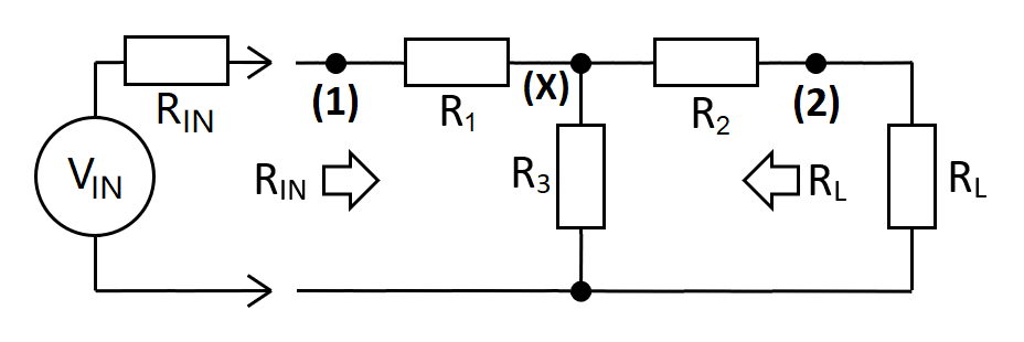
The taper-pad uses \(R_1\), \(R_2\) and \(R_3\) to match \(R_{IN}\) to \(R_L\). Circuit gain (\(A_{12}\)) is from input (1) to output (2). For example, if \(A_{12}\) is set to 0.25 then this is a 4:1 attenuation (-12.0412 dB).
|
\(\hspace{9cm}\)
Relevant Formulas $$A_{12(MAX)} = \frac{R_L}{R_{IN}}\left[1-\sqrt{1-\frac{R_{IN}}{R_L}}\text{ }\right]\hspace{0.5cm}R_L>R_{IN}$$ $$A_{12(MAX)} = 1-\sqrt{1-\frac{R_L}{R_{IN}}}\text{ }\hspace{2.0cm}R_{IN}>R_L$$ |
$$R_1 = R_L\left[\dfrac{1 + \dfrac{R_{IN}}{R_L}A_{12}^2 - 2\cdot A_{12}}{\dfrac{R_L}{R_{IN}}- A_{12}^2}\right]$$ $$R_2 = R_L\left[\dfrac{\dfrac{R_L}{R_{IN}}+ A_{12}^2 - 2\cdot A_{12}}{\dfrac{R_L}{R_{IN}}- A_{12}^2}\right]$$ $$R_3 = R_L\left[\dfrac{2\cdot A_{12}}{\dfrac{R_L}{R_{IN}}- A_{12}^2}\right]$$ |
| \(R_{IN}\) | Ω | \(\boxed{R_1=}\) | Ω | ||
| \(R_L\) | Ω | \(\boxed{R_2=}\) | Ω | ||
| \(A_{12}\) | V/V | \(\boxed{R_3=}\) | Ω | ||
| \(A_{12}\text{ (dB)}\) | dB | \(\boxed{A_{12(MAX)}=}\) | V/V | ||
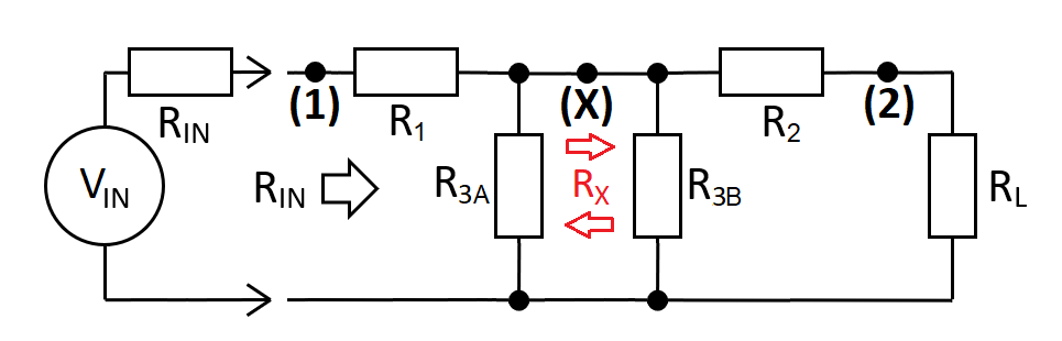
| Transfer values (applicable when analysing as two back-to-back L-Pads) | |||||
| \(\hspace{1cm} R_X\hspace{1cm}=\) | Ω | \(\hspace{1cm} R_3\hspace{1cm}=\) | Ω | ||
| \(\hspace{1cm} R_{3A}\hspace{0.9cm}=\) | Ω | \(\hspace{1cm} R_{3B}\hspace{0.8cm}=\) | Ω | ||
| \(\hspace{1cm} A_{1X}\hspace{0.9cm}=\) | V/V | \(\hspace{1cm} A_{X2}\hspace{0.8cm}=\) | V/V | ||
To derive the above equations we need to look at the basic gain relationships. Then, we can move on to distill these equations by considering the transfer impedance of two back-to-back L-pads. Firstly we'll find equations for \(R_1\), \(R_2\) and \(R_3\). These are indicated as (1), (2) and (3) directly below.
Noting that \(R_{IN} = R_3||(R_2+R_L) + R_1\):
Multiply by \(A_{X2} = \dfrac{R_L}{R_2+R_L}\) to obtain \(A_{12}\):
Rearrange:
(2) Use formulas from the resistive matching L-pad
(3) Modify and apply to left and right sections.
$$R_1=R_{IN}\sqrt{1-\dfrac{R_X}{R_{IN}}}\tag{4}$$ $$R_{3A} = \dfrac{R_{IN}\cdot R_X}{R_1}$$
$$R_2=R_{L}\sqrt{1-\dfrac{R_X}{R_{L}}}\tag{5}$$ $$R_{3B} = \dfrac{R_{L}\cdot R_X}{R_2}$$
$$R_X = A_{1X}\cdot (R_{IN} +R_1)$$
Noting that \(A_{X2} = \frac{R_L}{R_L+R_2}\), $$R_X = \dfrac{R_L-R_2}{A_{X2}}$$
$$A_{1X}\cdot (R_{IN} +R_1)= \dfrac{R_L-R_2}{A_{X2}}$$ $$A_{12}=\dfrac{R_L-R_2}{R_{IN}+R_1}\tag{6}$$ Then, we substitute in equation (6) for \(R_2\) from equation (2): -
$$A_{12}=\dfrac{R_L-R_L\left[\dfrac{R_{IN}-R_1}{A_{12}\cdot R_{IN}}-1\right]}{R_{IN}+R_1}$$ $$A_{12}\cdot\dfrac{R_{IN}+R_1}{R_L} = 2 - \dfrac{R_{IN}-R_1}{A_{12}\cdot R_{IN}}$$ $$A_{12}^2\cdot\dfrac{R_{IN}}{R_L}\cdot (R_{IN}+R_1)=R_1+2\cdot A_{12}\cdot R_{IN}-R_{IN}$$ $$A_{12}^2\cdot\dfrac{R_{IN}^2}{R_L}=R_1\left[1-A_{12}^2\cdot\dfrac{R_{IN}}{R_L}\right]+R_{IN}\left[2\cdot A_{12}-1\right]$$ $$R_1 = \dfrac{A_{12}^2\cdot\frac{R_{IN}^2}{R_L}-R_{IN}\left[2\cdot A_{12}-1\right]}{1 - A_{12}^2\cdot\frac{R_{IN}}{R_L}} \hspace{1cm}=\hspace{1cm}R_L\left[\dfrac{1+A_{12}^2\cdot\frac{R_{IN}}{R_L}-2\cdot A_{12}}{\frac{R_L}{R_{IN}}-A_{12}^2}\right]\tag{7}$$
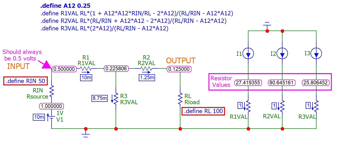
- The source (V1) is reduced from 1 volt to 0.5 volts hence the input impedance is 50 Ω
- The input is 0.5 volts and the output is 0.125 volts hence, \(A_{12}\) = 0.25
- 1 amp current sources "test" the values of R1, R2 and R3 (to the right)
- Those values match what the calculator produces at the top of this page